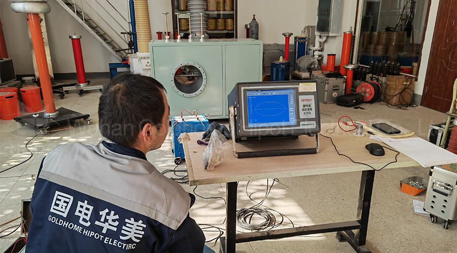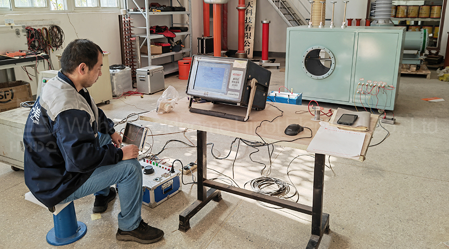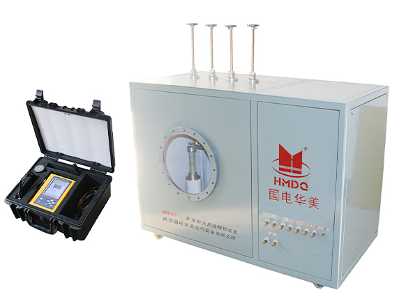
Partial Discharge Fault Simulation Test System For Switchgear
Applications:
- The components of the switchgear simulation experiment control device include a circuit breaker simulation device, a controller, and a control box,
- The control box includes a box body, control buttons and signal devices, control buttons and signal devices
- Small size, no need for large testing equipment, saving costs
- Suitable for large-scale simulated switchgear experiments
- It can visually control various components on the control box, with flexible installation and fixation, small size, and no need for a bulky test bench
-
 Strictly FAT Test
 - Third-party Calibration
-
Response within
24 hours -
Free warranty
12 month -
On-line training
Support
Profile:
Partial Discharge Fault Simulation Test System For Switchgear is Suitable for large-scale simulated switchgear experiments The various components on the control box can be intuitively controlled, with flexible installation and fixation, small size, and no need for a bulky test bench
Features:
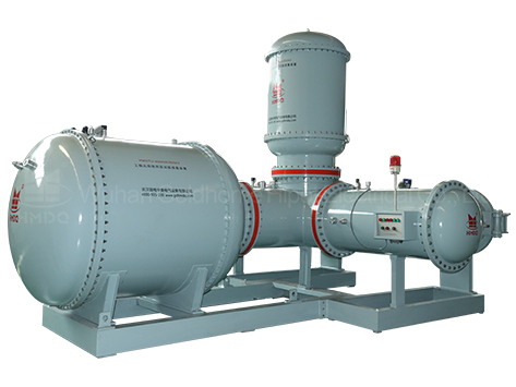
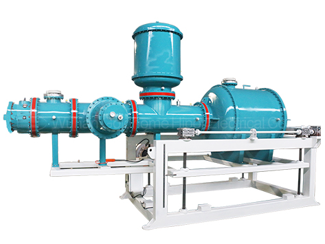
- Good authenticity: Designed according to the physical switchgear, simulate various partial discharge faults inside the switchgear realistically.
- Fault simulation: It can simulate discharge types such as switch cabinet tip, suspension, air gap, particles, and surface, and multiple discharges can be generated in combination.
- Controllable discharge: The discharge type can be selected arbitrarily, and the starting voltage, extinguishing voltage, and discharge intensity of each discharge signal can be controlled.
- Diversified detection: It can provide a testing platform for pulse current, ultra-high frequency, ultrasonic, transient ground voltage and other technical detection.
- Measurement transmission: Built in pulse current method related coupling and calibration units can synchronously detect the partial discharge level of the experimental device, which serves as the basis for instrument assessment.
- Good stability: Each discharge module can be reused, and the discharge characteristics are stable.
- Visualization: Equipped with an infrared video probe for easy observation of internal conditions and capturing discharge videos.
- Convenient operation: The occurrence and disappearance of various faults can be directly controlled outside the device.
- Safe and reliable: The boosting equipment is built-in, and the high voltage is isolated from the outside, ensuring safe and reliable operation.
Parameter:
- Rated voltage: 30kV.
- Rated capacitance: ≤ 100pF.
- Rated capacity: 3KVA~20KVA.
- Test frequency: 30Hz~300Hz.
- Input voltage: 0-220V.
- Instrument voltage: 0-100V.
- Partial discharge level: ≤ 1PC.
- Power frequency withstand voltage level: 30KV/1min.
- Simulated discharge types: tip discharge, particle discharge, surface discharge, gap discharge, suspension discharge
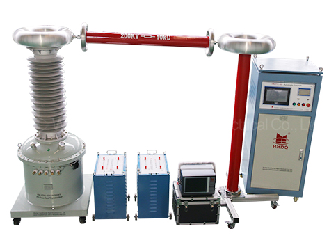
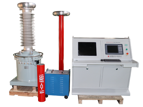
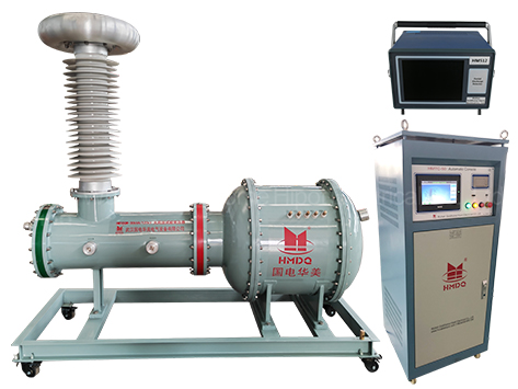
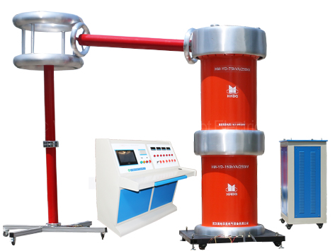
Pictures: