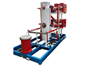
Impulse Current Test Systems
Applications:
Impulse current test systems are used to evaluate the ability of electrical equipment to withstand high-voltage impulses. These systems are crucial for testing the insulation and overall durability of devices such, as transformers, cables, and switchgear, particularly in high-voltage environments.
-
 Strictly FAT Test
 - Third-party Calibration
-
Response within
24 hours -
Free warranty
12 month -
On-line training
Support
Profile:
Impulse current test systems are used to evaluate the ability of electrical equipment to withstand high-voltage impulses.These systems are crucial for testing the insulation and overall durability of devices such,as transformers,cables,and switchgear,particularly in high-voltage environments.
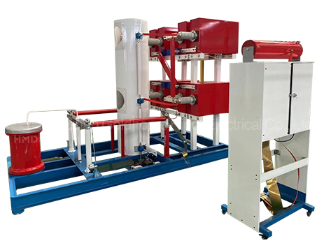
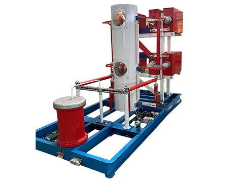
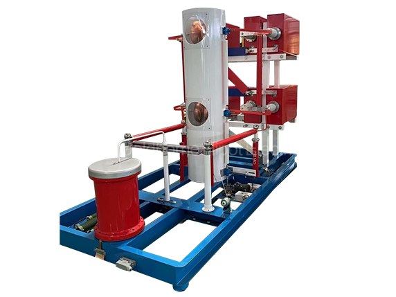
The impulse current test system typically consists of a high-voltage impulse generator,measurement and control equipment,and the test object itself.The generator produces high-voltage impulses that simulate lightning strikes or other transient voltage events,allowing engineers to assess the performance and reliability of the equipment under such conditions.
These tests are essential for ensuring the safety and reliability of electrical equipment,especially in critical infrastructure and high-voltage applications.They help manufacturers and operators identify potential weaknesses in their products and take necessary measures to improve their performance and durability.
Features:
- Charging device input power: 380V/50kV/20kVA, L-L two-phase, 50Hz/60Hz
- Maximum charging voltage: 50kVDC±10%, maximum charging current 0.5A, actual charging voltage is not higher than 45kV
- Pulse capacitor : 26kV/60μF
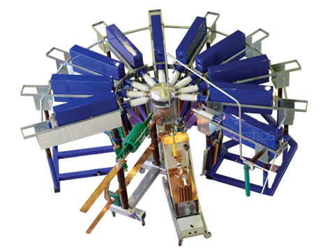
- Number of capacitors: 16 sets, total pulse energy 300kJ
- Each group of capacitors is mounted on a fixed bracket for stable positioning, and multiple capacitors can be operated in parallel and freely combined.
- Trigger gap voltage range: 1kV~50kV;
- Duration of use: under 100% rating, charge and discharge once every 120s, and can work continuously.
- The discharge gap is controlled synchronously by tungsten copper gap, and the control accuracy is ± within 0.5mm;
- Improve the energy efficiency ratio of equipment, balance investment costs, and be suitable for research institutions, research institutes and other units and laboratory applications
- Discharge circuit footprint: W*L*H=3.5m*4.5m*2.0m
- Total weight: about 2 tons
Parameter:
1.Input voltage: AC 2 Phase, 50HZ, 380V/50kV/20kVA
2.The current waveform is 8/20μs. The residual voltage of SPD is not more than 5kV;
The allowable error of the waveform:
- Ipeak:±100kA ±10%;
- T1: 8μs ±10%;
- T2: 20μs ±10%。
4.The current waveform is 10/350μs. The residual voltage of SPD is not more than 5kV;
Allowable error of waveform:
- Ipeak:±50kA ±10%;
- T1: 10μs ±10%;
-T2: 350μs ±20%。
5.The small overshoot or amplitude of the shock waveform should not be greater than 5% of the peak. The current value of the reverse should not be greater than 20% of the peak value; Maximum charging voltage: DC45kV, maximum charging current 0.5A;